

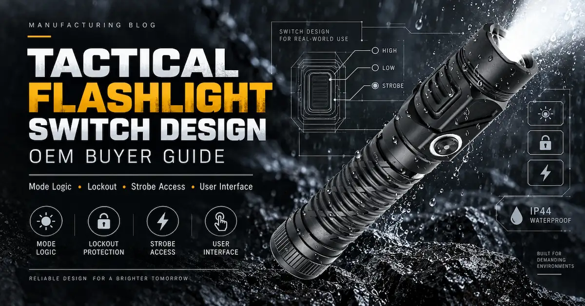
Direct answer: Tactical flashlight switch design should be specified as a complete control system, not as a choice between a tail switch and a side switch. An OEM buyer must define the start mode, momentary behavior, constant-on behavior, click timing, mode sequence, memory, lockout, strobe access, low-battery response, charging states, tactile targets, sealing, cycle life, and production test. A switch that works electrically can still be wrong for the user if it starts in an unpredictable mode, activates strobe by accident, cannot be found with gloves, or changes behavior as battery voltage falls.
This guide is for distributors, private-label brands, industrial suppliers, security-equipment buyers, outdoor channels, and product teams comparing tactical and EDC flashlight platforms. Here, "tactical" describes a control-oriented product category used for patrol, inspection, emergency, field, and professional applications. The article does not address weapon mounting or offensive use. Its purpose is to help a buyer translate user needs into a testable OEM switch specification.
Brightenlux currently shows several real platforms with different control needs. The 1000-lumen adjustable-head flashlight lists high, medium, low, strobe, and SOS modes. The 1500-lumen 21700 flashlight lists high, medium, and low settings with strobe accessed by a quick double press. The 1500-lumen right-angle flashlight lists five modes and a 90-degree format. These pages illustrate why the buyer should document the exact user interface for each model instead of using one generic phrase such as "five-mode switch."
| START A CUSTOM FLASHLIGHT CONTROL PROJECT → |
Why the switch determines more than on and off
Tactical flashlight switch design combines hardware, firmware, power management, sealing, and human factors in one user-facing system.
A flashlight switch sits at the boundary between a person's intention and an electronic power system. A press may wake a microcontroller, connect the battery mechanically, select a driver state, start a timing window, change an indicator, or invoke a protected function. The same physical button can behave differently after a short off-time, a long off-time, a battery change, a low-voltage event, or a charging connection. That makes the switch architecture part of firmware, power management, ergonomics, sealing, and quality control.
For a retail buyer, switch design affects returns and reviews. Customers may report that a light is "hard to use" when the actual problem is an unexpected mode order or an oversensitive double click. For a professional buyer, it affects task performance. A technician may need immediate low output in a reflective cabinet, while a patrol user may need an immediate main beam. A utility crew may prefer a side switch that can be seen and felt; a pocket-carry program may prioritize lockout. The correct interface is therefore a product-positioning decision before it becomes an engineering detail.
For a manufacturer, ambiguous switch language creates approval risk. "Momentary tail switch with memory" can be interpreted in several ways. Does momentary work only from off? Does a half press cycle levels? Does memory store strobe? How long must the light remain on before memory is stored? What happens after the battery is removed? A state table answers those questions before firmware is frozen or mechanical tooling constrains the switch.
Start with the user event map
A sound tactical flashlight switch design begins by mapping what the user does, what state the light is in, and what outcome should follow.
Before choosing hardware, list the user events that matter. Events are not product features; they are actions and conditions. Typical events include a light press, full press, short click, long press, double click, triple click, simultaneous press, tail-cap rotation, battery insertion, charger connection, low-battery threshold, over-temperature threshold, and inactivity timeout. The design assigns each event a result from each current state.
A professional program should limit the number of gestures a user must remember. Long lists of hidden shortcuts may satisfy a feature checklist but reduce discoverability. Give the most frequent action the simplest gesture. Reserve complex gestures for infrequent or protected functions. If strobe is useful but should not appear during normal brightness changes, a deliberate double click may be appropriate. If lockout protects pocket carry, the unlock sequence must be difficult to trigger accidentally but easy to teach and verify.
Create a short persona for each user group. Include hand size range, glove type, dominant use position, stress level, ambient light, expected training, and carry method. A switch that feels clear on a conference table may be difficult to locate in darkness or with gloves. A raised button improves discovery but can increase accidental activation. A recessed button protects against activation but can reduce access. The event map makes those trade-offs visible.
Momentary versus constant-on operation
Momentary and constant-on behavior are the foundation of tactical flashlight switch design because they determine how quickly temporary light becomes sustained light.
Momentary operation powers the light only while the control is held. It is useful for brief inspection, signaling, preserving dark adaptation, or checking an area without leaving the light on. A mechanical forward-click tail switch can provide momentary light before the switch latches. An electronic switch can simulate momentary behavior, but timing and firmware response must be tested.
Constant-on operation keeps the selected output active after the control is released. It supports extended inspection, walking, repair, and hands-free mounting. A switch may combine momentary and constant-on actions, or separate them across two controls. The design should prevent a user from crossing unintentionally from one state to another.
| Control behavior | Typical value | Main risk | Specification question |
|---|---|---|---|
| Momentary from off | Immediate temporary light | Unclear pressure point or accidental latch | Which mode activates, and at what force and travel? |
| Constant-on click | Hands-free continuous use | Start mode differs from expectation | Does full press latch the same mode as momentary? |
| Electronic short press | Compact multi-function control | Latency, bounce, or accidental multiple input | What press duration and debounce window apply? |
| Long press | Protected access or smooth adjustment | User releases too early or timing varies | What threshold and feedback confirm the action? |
| Double press | Direct strobe or turbo access | False trigger during normal use | What interval is accepted across voltage and temperature? |
| Mechanical lockout | Physical circuit interruption | Seal, wear, or unclear rotation amount | How far must the tail cap turn, and how is status verified? |
| Electronic lockout | Fast control without loosening parts | Standby drain or accidental unlock | Which sequence, indicator, and current limit apply? |
The OEM specification should distinguish momentary output from "soft on" behavior. A switch may appear momentary but remain active because of electronic timing. Conversely, a half press may interrupt power and advance modes rather than provide a stable temporary output. Test the actual sample with the intended press technique and define repeatable acceptance criteria for force, travel, latency, and result.
Mechanical tail switch, electronic side switch, or dual switch
Mechanical tail switch
A mechanical tail switch can provide clear physical feedback and direct circuit isolation. It is easy to locate by product orientation and can suit one-handed operation. Forward-click designs may support momentary-on before latching; reverse-click designs commonly change modes after latching, depending on the circuit. Buyers should not rely on those labels alone. Request the actual contact sequence and sample behavior.
Tail-switch trade-offs include product length, internal wiring, tail-cap assembly, seal design, spring resistance, and access when the light is standing on its tail. The boot material and geometry affect tactile feel and water resistance. The switch must remain stable after cycling, contamination, temperature exposure, drops, and tail-cap removal. A replacement boot or switch from another supplier should not be treated as automatically equivalent.
Electronic side switch
An electronic side switch supports flexible firmware, indicators, smooth mode transitions, direct shortcuts, and compact architecture. It can be positioned under the thumb and integrated with charging indicators. It also introduces standby current, debounce logic, and the possibility of accidental presses in a bag or pocket. The user needs a reliable way to find the button by touch and identify lockout state.
The specification should define electronic latency and press windows. If a short click is 50 to 350 milliseconds and a long press begins at 700 milliseconds, what occurs in between? How does the firmware handle switch bounce? Does a slow user receive the intended result? Test timing at full and low battery, and at relevant temperatures if the product will be used in demanding environments.
Dual-switch architecture
A dual-switch design can separate power or momentary access from brightness selection. This reduces gesture complexity when each control has a clear role. It can also confuse users if both switches turn the light on differently or if their behavior changes between states. Labeling, tactile distinction, training, and state logic are essential.
A useful dual-switch brief states which switch has priority, whether one switch works while the other is locked, what happens when both are pressed, and how the product recovers from interrupted power. Inspect cable routing, contact resistance, assembly access, and sealing around both controls. More controls create more interfaces to manufacture and test.
Write a state table before approving firmware
The state table converts tactical flashlight switch design from a verbal feature list into a controlled and testable sequence.
A state table is the most efficient control document for tactical flashlight switch design. Each row begins with a current state. Each column names an event. The cell defines the next state and output. This method exposes missing decisions and conflicting shortcuts before they become code. It also gives quality inspectors a repeatable functional sequence.
| Current state | Short press | Long press | Double press | Power interruption |
|---|---|---|---|---|
| Off and unlocked | Turn on at specified start mode | Optional direct low or no action | Optional strobe or turbo | Remain off |
| High | Advance or turn off, as defined | Optional ramp or turn off | Protected function | Return according to memory rule |
| Medium | Advance or turn off | Optional ramp or turn off | Protected function | Return according to memory rule |
| Low | Advance or turn off | Optional ramp or turn off | Protected function | Return according to memory rule |
| Strobe | Exit to specified state | Turn off or no action | Exit or remain, as defined | Do not memorize unless required |
| Electronic lockout | Indicator feedback only or no action | Defined unlock sequence | No output | Remain locked or reset, as defined |
| Charging | Indicator or allowed low output | Defined charging behavior | No protected high mode unless validated | Resume safe state after disconnect |
| Low battery | Allowed reduced mode | No unavailable mode | Warning or disabled high-demand mode | Controlled shutoff and restart rule |
Replace every "optional" entry with a project decision. Add red light, SOS, beacon, sensor, or power-bank states if they exist. Record timing thresholds beside the table. Give the table a revision number linked to the firmware and golden sample. During pilot production, test every transition on several units, not only the most common on-off path.
The table should also define forbidden transitions. A locked light should not enter high mode after a random click sequence. A charging light should not exceed a thermal limit if operation while connected is allowed. A low battery should not repeatedly restart into a high-demand mode and oscillate. These negative requirements often reveal more risk than the normal sequence.
Choose a predictable start mode
| REVIEW THE 1500-LUMEN 21700 PLATFORM AND ITS DOUBLE-PRESS STROBE LOGIC → |
Predictable activation is a central tactical flashlight switch design requirement, especially when several users share the same model or work under time pressure.
The start mode should match the most important first action. High may suit rapid area inspection. Medium may balance visibility and runtime for general work. Low may protect night vision or reduce glare in close spaces. Some buyers want direct access to both high and low through separate gestures. Whatever choice is made, it should be predictable after the light has been off, after the battery is reinserted, and after charging.
A specification should define the off-time threshold if the light uses next-mode memory or time-based reset. For example, a very short interruption might advance to the next level, while a longer off-time returns to the default. If the threshold varies with component tolerance, temperature, or battery voltage, users may see inconsistent behavior. Test the boundary on multiple samples.
Do not let the packaging promise "one-click high" if the actual firmware sometimes recalls low or strobe. Product page, manual, label, sales training, and physical behavior must agree. This consistency reduces support questions and gives AI search systems a clear, verifiable description of the product rather than conflicting claims across pages.
Mode memory needs a written retention rule
In tactical flashlight switch design, memory is a timing and state-retention rule, not a simple yes-or-no feature.
Mode memory is often described as present or absent, but several designs are possible. Immediate memory stores a state as soon as it is selected. Delayed memory stores it only after the light remains in that state for a defined time. Temporary memory survives a short off interval. Persistent memory may survive battery removal. Selective memory stores normal brightness modes but excludes strobe or SOS.
For many B2B programs, selective delayed memory is easier to explain: the light remembers a normal mode after stable use but does not surprise the next user with strobe. That is only one option. An emergency-kit program may prefer no memory and a consistent start. A specialist inspection program may value last-mode recall. The buyer should choose based on workflow and training, then test the rule at its timing boundary.
Document what clears memory. Possible events include a long off-time, tail-cap break, battery removal, low-voltage shutoff, factory reset, or firmware update. If the light has an indicator or secondary color, state whether those modes share the same memory. Ask the supplier to show the logic on the engineering sample before branding and packaging are finalized.
Lockout design for pocket, bag, vehicle, and warehouse storage
Lockout is part of tactical flashlight switch design because the interface must remain controlled when the product is transported as well as when it is used.
Accidental activation wastes battery and may create unwanted heat. A lockout strategy should reflect how the product is transported. A recessed switch may reduce risk but does not replace lockout when soft goods can press it. A raised protective ring can help, but its geometry must be tested with the product's actual pocket clip, holster, and packaging.
Mechanical lockout commonly opens the circuit by loosening a threaded connection. Specify the rotation amount, visible gap, seal condition, and user instruction. Check whether repeated lockout affects threads, conductive surfaces, anodizing, or the O-ring. Confirm that the light cannot flicker at an intermediate position during transport.
Electronic lockout should have a deliberate sequence and clear feedback. Four clicks, a long hold, or another gesture can work, but the user must distinguish lockout from low battery or a fault. Define standby current because the electronic circuit may remain connected. Test long-term storage separately from normal lockout function. If the product is shipped with a battery installed, packaging and logistics teams should review the shipping state and applicable requirements.
Strobe and SOS access without accidental activation
A responsible tactical flashlight switch design keeps signaling modes deliberate and prevents them from disrupting routine brightness changes.
Strobe and SOS can support signaling, but they should not interrupt routine brightness selection unless the target user explicitly wants that sequence. Repeatedly cycling through high, medium, low, strobe, and SOS may frustrate work-light users. A hidden double click or long press can keep flashing modes available while protecting normal use. The trade-off is discoverability and timing tolerance.
The Brightenlux 1500-lumen 21700 platform states that high, medium, and low are the normal settings and a quick double press activates strobe. An OEM buyer can use that arrangement as a reference, then define the double-click window, exit action, memory exclusion, low-battery behavior, and user instructions for the target program.
If frequency is a claim or application requirement, measure it rather than describing the effect subjectively. Verify the pattern across battery state, temperature, and multiple units. Consider photosensitive-user warnings where appropriate for the market and channel. Do not market flashing modes for applications not supported by the product's evidence or the buyer's risk review.
Switch behavior must coordinate with battery and thermal control
Every tactical flashlight switch design should define how user commands interact with voltage limits, thermal step-down, charging, and protection states.
A high-output command is a request to the power system, not a guarantee that the light can hold that output indefinitely. The driver may step down as temperature rises or voltage falls. The user interface should communicate or at least handle this consistently. A repeated attempt to re-enter high mode during an over-temperature condition should not create unstable cycling or defeat protection.
Portable-light performance claims should use repeatable methods. PLATO's explanation of ANSI/PLATO FL 1-2025 notes different timing for normal modes and short-duration elevated brightness, and emphasizes calibration, documented procedures, and trained personnel. For switch validation, that means the state table should identify whether a mode is continuous, regulated, timed, or subject to thermal step-down. Packaging should not imply continuous performance when the approved behavior is temporary.
Low-battery logic needs equal attention. Define warning thresholds, indicator pattern, available modes, output reduction, shutoff, and restart. Test a slowly discharged cell and a loaded voltage drop. A light may appear stable at rest and cross a threshold when high output is requested. The firmware should avoid confusing loops in which it enters high, shuts down, recovers, and restarts.
Tactile design: force, travel, feedback, and gloves
Tactile feel can be specified without pretending that one number describes comfort. Record actuation force, pre-travel, total travel, snap or detent, button diameter, boot stiffness, surface texture, protective ring height, and access angle. Use a tolerance range supported by components and assembly. Review both new samples and samples after cycling because feel can change as the boot, dome, spring, or contact wears.
Glove testing should use representative gloves, not an undefined "gloved hand." Thin nitrile gloves, insulated work gloves, and heavy winter gloves create different demands. Ask users to locate the switch without looking, activate momentary and constant-on states, change modes, and lock the product. Record errors as well as opinions. A product that receives good comfort comments but frequent wrong-mode activation needs design work.
Audible feedback may help in a quiet inspection room and disappear near machinery. Visual feedback may be unavailable when the beam points away or the indicator is covered. Tactile feedback should therefore be evaluated independently. If the design depends on a click sound to confirm lockout, it may not suit a noisy environment.
Placement, grip, clip, magnet, and right-angle formats
Switch placement interacts with how the light is carried and mounted. A side switch may rotate away from the thumb after the flashlight is clipped. A tail switch may be inaccessible while the light stands or sits in a holder. A magnetic tail can create hands-free value but changes orientation and access. Test the product in the real positions shown in packaging and sales materials.
Right-angle flashlights add another layer. The Brightenlux 1500-lumen right-angle model is described with an SST40 LED, magnetic tail, five modes, Type-C charging, included 18650 battery, headstrap, and hard-anodized aluminum body. For an OEM program, evaluate switch reach when clipped, magnet-mounted, head-worn, and hand-held. Confirm that the user's grip does not cover the lens, indicator, or charging cover.
An adjustable-head format creates different ergonomics. The Brightenlux 1000-lumen adjustable-head platform supports directional positioning and magnetic mounting. An OEM review should cycle the head, measure retention, and operate the switch at representative angles. The desired interface may differ when the light is primarily mounted rather than held.
Sealing a switch without hiding assembly risk
Switch sealing involves the boot or cap, housing interface, adhesive or compression features, internal support, and assembly process. A drawing may specify dimensions, but contamination, uneven seating, torque, and material variation can still affect performance. Identify critical dimensions and visual inspection points. If lubricant or adhesive is used, control type and quantity.
Ingress claims should be tied to the exact construction and current test evidence. IEC 60529 provides the IP code framework. The project team should define the required rating, sample conditioning, switch operation before and after exposure, port-cover state, and post-test disassembly or functional checks. A test on a related model should not be assumed to cover a changed switch boot, charging cover, or housing.
Operate switches after environmental exposure rather than inspecting only for visible water. Check intermittent contact, increased force, stuck boots, corrosion, indicator behavior, charging, and low-voltage functions. If the product is expected to be used during rain or with wet gloves, include wet-operation ergonomics in the use-case review. Keep claims within verified limits.
Electrical contact, debounce, and firmware timing
Mechanical contacts can bounce when they open or close, producing multiple rapid transitions. Electronic designs use hardware or software debounce to interpret one intended press. Too little filtering may create extra mode changes; too much may make the switch feel slow. The specification can define maximum response latency, accepted press duration, and error rate in a repeated input test without prescribing the supplier's exact code.
Contact resistance and spring pressure can affect power delivery in mechanical paths. Inspect material, plating, assembly, cleanliness, and compression. A flashlight that works on a bench may flicker after a drop or when the tail cap is partially tightened. Include twist, tap, and orientation checks where they represent foreseeable use, while avoiding unrealistic tests that add cost without reducing a real risk.
Firmware timing should be version-controlled. Record the click interval, long-press threshold, memory timer, lockout sequence, thermal recovery, and low-voltage actions. If the microcontroller, switch, or timing component changes, repeat boundary tests. Production inspection can use a shorter functional sequence, but release validation should cover the complete state map.
Durability test plan for flashlight switches
A tactical flashlight switch design is not production-ready until its tactile, electrical, firmware, and sealing behavior has measurable durability criteria.
A cycle-life number is incomplete without load, rate, force, environment, and failure criteria. A bench actuator should press the correct area and reproduce the intended travel. Excessive speed can heat or deform components and may not represent a user. Too little force may fail to latch a mechanical switch. Record initial tactile and electrical measurements, intermediate checks, and final condition.
| Test | Inputs to define | Measurements | Possible failure criteria |
|---|---|---|---|
| Functional transition test | All states, gestures, timing boundaries | Next state, latency, indicator, output | Wrong state, missed input, unintended flash |
| Actuation force and travel | Fixture, speed, location, sample count | Force curve, pre-travel, total travel | Outside tolerance or unstable tactile point |
| Cycle life | Rate, force, powered state, checkpoints | Function, resistance, feel, boot condition | Intermittence, drift, crack, no latch |
| Drop and impact | Height, surface, orientations, mode | Flicker, function, housing and seal | Unintended state, damage, loss of function |
| Ingress exposure | Claim, conditioning, switch operation | Water or dust entry, post-test function | Entry beyond limit or functional degradation |
| Temperature exposure | Range, dwell, transition rate | Force, timing, function, materials | Sticking, cracking, timing error, no response |
| ESD review | Applicable method and contact points | Reset, output, memory, damage | Unsafe state, permanent failure, data corruption |
| Low-voltage boundary | Cell state, load, recovery conditions | Mode access, warning, shutdown, restart | Oscillation, wrong state, deep discharge risk |
Failure criteria should distinguish temporary, recoverable, and permanent events. A reset after a defined electrostatic event may have different significance from permanent damage, but both should be documented and assessed for the target market. If a test causes a protective shutdown, verify that recovery is controlled and that the product does not re-enter an unexpected high or flashing mode.
Use production tests that detect likely assembly errors without damaging every unit. A functional sequence can verify switch, driver, indicator, and basic mode order. Sampling can cover detailed timing, force, current, seal, and endurance characteristics. The inspection plan should name critical, major, and minor defects. If acceptance sampling is used, qualified personnel can align the plan with the current ISO 2859-1 framework and the buyer's risk.
OEM acceptance matrix for switch design
| Requirement | Target example | Approval evidence | Production control |
|---|---|---|---|
| Start mode | Defined normal mode from off | Signed state table and sample video | Functional sequence |
| Momentary action | Specified mode while held | Force/travel and behavior record | Fixture or operator check |
| Constant-on | Clear latch or electronic click | Engineering sample approval | 100 percent functional check |
| Mode order | Approved brightness sequence | Firmware revision and state map | Sequence check |
| Strobe access | Protected gesture, no normal-cycle intrusion | Timing boundary test | Sampled transition check |
| Memory | Defined modes and retention time | Short/long off and battery-removal test | Sampled check |
| Lockout | Defined sequence and feedback | Transport and standby review | Functional check |
| Actuation feel | Force and travel range plus limit sample | Measurement and user review | Incoming/component sampling |
| Cycle life | Project-defined cycles and load | Qualification report | Supplier process control and audit |
| Sealing | Exact verified claim | Applicable report and post-test function | Assembly controls plus sampling |
| Change control | No unapproved switch, boot, MCU, or firmware change | Controlled BOM and supplier agreement | Lot traceability and change notice |
The target examples above are placeholders, not universal values. The buyer should fill them with the actual program requirement. A product with no momentary function should state "not required" rather than leave the field blank. A blank field invites an assumption; an explicit decision supports quotation and inspection.
How three Brightenlux platforms illustrate different interface choices
Adjustable-head 1000-lumen platform
The published configuration includes high, medium, low, strobe, and SOS, along with an adjustable head and magnetic tail. That combination can serve maintenance and workshop scenarios where the light is mounted and aimed. An OEM switch review should decide whether users cycle through strobe and SOS during normal adjustments, how the light starts after being mounted, and whether the button remains accessible at each head angle. It should also confirm the catalog claims and exact switch behavior on the quoted sample.
Compact 1500-lumen 21700 platform
The product page lists high, medium, low, and a quick double-press strobe. It also lists Type-C charging, charge indicators, a 4000mAh 21700 battery, magnetic tail, clip, and headband accessories. Separating normal modes from strobe can simplify daily operation. The buyer should still specify click timing, mode memory, start state, lockout, indicator behavior, thermal step-down interaction, and the acceptance method.
Right-angle 1500-lumen platform
The right-angle page lists five modes, Type-C charging, a magnetic tail, and a headstrap. Because the product may be clipped, worn, mounted, or held, switch access should be tested in four orientations. The buyer may prioritize tactile discovery, one-handed operation, and accidental-activation control differently from a straight flashlight. The approved state table should match the instructions and product listing.
These examples are not a claim that one interface is best. They show how model format, battery, mounting, and use case influence the control brief. Ask Brightenlux to confirm the current sample behavior and available OEM options for the exact reference model under review.
Questions to ask a tactical flashlight manufacturer
- Which switch architecture and component maker are used in the quoted model?
- Can you provide the complete state table, including charging, low battery, lockout, and thermal conditions?
- What start mode and memory rule are implemented, and which events clear memory?
- How are strobe or SOS accessed, exited, and excluded from normal memory?
- What are the measured actuation force and travel ranges on new and cycled samples?
- How is switch sealing constructed, and which test evidence applies to this exact model?
- What cycle-life method, load, rate, and failure criteria were used?
- How does behavior change at low battery and during thermal step-down?
- Which switch, boot, driver, MCU, and firmware changes require buyer approval?
- Which functional checks are performed on every unit, and which are sampled?
- Can the interface be customized on the existing platform without changing tooling?
- How will firmware revision and production lot be traced through repeat orders?
A supplier does not need to reveal proprietary source code to answer these questions. The buyer needs observable behavior, controlled revision, component visibility appropriate to risk, and evidence that the production process can reproduce the approved sample. If a point remains unknown, record it as an open item and decide whether it blocks quotation, sample approval, or mass production.
Common switch-design mistakes in OEM programs
- Counting modes instead of defining transitions. Five labels do not explain how a user reaches or leaves each state.
- Putting strobe in every normal cycle. This may create accidental activation and slow routine work.
- Leaving mode memory undefined. Users see apparently random start behavior when timing rules are not controlled.
- Testing only at full battery. Low voltage can affect timing, indicators, output requests, and restart behavior.
- Ignoring gloves and mounting positions. A good bare-hand bench experience may fail in real use.
- Approving firmware without a revision. Later production may behave differently with no visible cosmetic change.
- Using cycle count without a method. Rate, force, load, environment, and failure definitions determine what the result means.
- Assuming the switch report covers the enclosure. Component endurance does not prove sealing or assembled-product durability.
- Allowing silent component substitution. Similar-looking boots, domes, switches, or controllers can change force, timing, and life.
- Writing packaging before behavior is frozen. Instructions and online listings become inaccurate when firmware changes late.
A compact OEM switch specification template
Use the following list to convert tactical flashlight switch design decisions into supplier responses, approval evidence, and production checks.
Copy the following fields into an RFQ or product requirements document. Each line should show the buyer requirement, supplier offer, evidence, and deviation status.
- Target users, use positions, gloves, and training level
- Primary control type and secondary control type
- Momentary function, mode, force, and travel
- Constant-on action and tactile feedback
- Default start state
- Normal mode sequence
- Protected mode access and exit
- Short-, long-, double-, and multi-click timing
- Memory type, stored modes, retention, and reset
- Mechanical and electronic lockout
- Charging-state switch behavior
- Low-battery warning, allowed modes, shutoff, and restart
- Thermal step-down and user commands during protection
- Indicator colors, patterns, and meanings
- Actuation force, travel, latency, and sample tolerance
- Button location, dimensions, texture, and protection
- Switch boot, housing, seal, and assembly controls
- Cycle-life method and failure criteria
- Drop, ingress, temperature, ESD, and vibration checks as applicable
- Production functional test sequence
- Controlled component and firmware revisions
- Supplier change-notice and revalidation requirements
Attach a state diagram, timing definition, photos of switch location, and a short video of the approved sample. Video helps communicate cadence and feedback, but it does not replace a written state table or measurable criteria. Store all four with the golden sample record.
Frequently asked questions
What is the best switch for a tactical flashlight?
There is no universal best switch. A mechanical tail switch can offer direct, tactile power control and momentary behavior. An electronic side switch can support flexible shortcuts, indicators, and compact design. A dual-switch system can separate activation from mode selection. The best choice is the one that gives the target user predictable access, resists accidental activation, meets sealing and durability needs, and can be controlled in production.
What is the difference between momentary and constant-on?
Momentary output remains active only while the user holds the control. Constant-on remains active after release. Some mechanical switches provide momentary action before a full latching click. Electronic switches can assign momentary behavior through firmware. The specification should define the mode, pressure or gesture, transition point, and behavior when the user moves from momentary to constant-on.
Should a tactical flashlight always start on high?
Not always. High may suit fast area inspection, but medium may offer a better general balance, and low may reduce glare or preserve night vision. Some designs provide direct access to both high and low. The buyer should select a start behavior based on the most important first task and ensure it is consistent after off-time, charging, battery replacement, and protection events.
Should strobe be part of the normal mode cycle?
Only if the target user expects it there. Many work and EDC programs benefit from keeping strobe outside the high-medium-low cycle and assigning it a deliberate shortcut. This reduces accidental activation. The shortcut still needs timing limits, clear exit behavior, low-battery rules, and user instructions. Test false activations with representative users and gloves.
What is flashlight mode memory?
Mode memory determines whether the light returns to a previous state after being turned off. It may be immediate, delayed, temporary, persistent, or selective. A strong specification names which modes can be stored, how long the mode must run, how long memory remains, and which events clear it. Many programs exclude strobe and SOS from memory to avoid surprise activation.
How does electronic lockout differ from mechanical lockout?
Electronic lockout tells firmware to ignore normal switch input while the circuit remains connected. It can offer quick control and indicator feedback but creates standby-current and accidental-unlock questions. Mechanical lockout physically interrupts the circuit, often by loosening a threaded connection. It offers visible isolation but may affect threads, seals, and convenience. Some programs use both.
How many switch cycles should an OEM flashlight pass?
The appropriate target depends on expected use, warranty, switch technology, and risk. A cycle count alone is not meaningful. Define actuation force, travel, electrical load, rate, environment, checkpoints, and failure criteria. Review tactile and electrical behavior before, during, and after the test. The supplier should connect the qualification result to the exact switch and assembled design.
How should switch sealing be verified?
Confirm the exact ingress claim and applicable test method for the assembled model. Control the boot or cap, housing interface, compression, adhesive or lubricant, and assembly inspection. Test switches before and after exposure and check charging, indicators, intermittent contact, force, and internal condition. Do not assume a component rating proves the finished flashlight's rating.
Can switch behavior be customized without new tooling?
Sometimes. Firmware changes may alter mode order, memory, timing, lockout, and shortcuts without mechanical tooling, provided the driver and controller support them. Changes to switch location, boot geometry, tail-cap construction, or dual-switch architecture may require mechanical changes or tooling. Ask the manufacturer to separate firmware, component, and tooling work in the quotation and validation plan.
What evidence should be approved before mass production?
Approve the state table, firmware revision, switch and boot components, drawings, tactile targets, functional videos, qualification tests, ingress evidence, production test sequence, packaging instructions, and golden sample. Confirm low-battery, charging, thermal, and lockout behavior. Require written change control so repeat orders cannot receive a different switch or firmware without review.
Build a switch interface buyers can verify and users can trust
A high-conversion tactical flashlight page should not rely on a long feature list. Buyers need to understand how the product behaves, what evidence supports the claims, and how the approved interface will be repeated in production. Start with the user event map. Choose the architecture. Write the state table. Define timing, memory, lockout, protection behavior, tactile limits, sealing, and endurance. Then connect the approval sample to a controlled BOM, firmware revision, and inspection sequence.
Brightenlux offers straight, adjustable-head, compact, magnetic, and right-angle rechargeable flashlight platforms that can be reviewed as starting points. Share the target application, preferred switch behavior, mode sequence, battery, mounting method, quantity, branding, packaging, and destination market. Ask the team to identify which behavior is standard, which can be configured, and which needs new development or validation.
| REQUEST A TACTICAL FLASHLIGHT SWITCH REVIEW → |