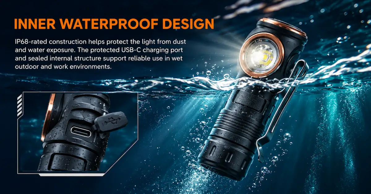


Quick Answer: Before approving tooling with a custom flashlight manufacturer, buyers should verify that the CAD design matches the physical assembly requirements of the finished flashlight. Critical checks include lens and LED alignment, adjustable-head movement, charging-port access, battery compartment fit, switch positioning, seals, and mounting interfaces. A reliable approval process combines controlled engineering drawings, tolerance analysis, representative prototypes, functional testing, and documented design revisions before manufacturing investment.
A flashlight can look perfect in a 3D rendering but fail during physical assembly.
The charging cable may not fully engage because the port is recessed too deeply. A redesigned lens holder may interfere with the LED mounting position. An adjustable head may rotate smoothly in CAD but become difficult to operate after the housing is assembled.
These issues are especially important when an overseas brand commissions a customized flashlight rather than purchasing an unchanged catalogue product.
For purchasing managers, a design mistake discovered after tooling approval can introduce extra engineering work, revised components, production delays, and unexpected costs.
The problem is not always a poorly designed individual part.
A flashlight may contain correctly manufactured components that do not fit or function correctly when assembled together.
This guide explains how to identify those risks before tooling approval.
It uses published products from Ningbo Brightenlux Electric Appliance Co., Ltd. as practical references while distinguishing existing product features from proposed OEM engineering changes.
For a broader overview of customization routes, buyers can also review the Brightenlux OEM Flashlight Customization Guide .
1. Why Can a Flashlight CAD Design Fail During Physical Assembly?
A CAD model describes the intended geometry of a product.
It can help engineers examine component arrangements, identify interference, and communicate the design to suppliers.
However, a CAD assembly does not automatically prove that the flashlight can be manufactured consistently.
Nominal dimensions do not represent every finished part
A digital model often shows parts at their nominal dimensions.
Actual manufactured components have dimensional variation within specified tolerances.
When multiple components are assembled, those variations can accumulate.
A design that appears to have sufficient clearance in CAD may have insufficient clearance at certain permitted dimensional combinations.
Materials behave differently
A flashlight may combine aluminum housings, polymer components, lenses, electrical contacts, sealing materials, and electronic assemblies.
Manufacturing methods and material properties influence how these parts fit together.
A component made from injection-molded plastic may require a different tolerance strategy from a machined aluminum component.
Assembly introduces additional constraints
Fasteners, threads, seals, retaining rings, and battery contacts can affect the final position of components.
A correct standalone part does not guarantee correct assembly.
Common CAD-to-Sample Problems
| Design Area | Potential Problem | Commercial Consequence |
|---|---|---|
| Lens and LED assembly | Incorrect spacing or alignment | Poor optical performance or rework |
| Adjustable-focus head | Insufficient clearance | Rough or restricted movement |
| USB-C connector | Port inaccessible to approved cable | Charging complaints |
| Battery compartment | Incorrect fit or contact engagement | Assembly or reliability problems |
| Switch interface | Button interference or poor alignment | Inconsistent operation |
| Sealing components | Incorrect groove or compression | Ingress-protection concerns |
| Belt clip | Interference with housing or controls | Poor usability |
| Magnetic tail assembly | Incorrect seating or retention | Mounting-performance concerns |
Buyer takeaway: CAD approval should be followed by measurable assembly and functional verification before the design is frozen for production.
2. Which Buyers Need Detailed CAD-to-Sample Verification?
Not every flashlight purchase requires new engineering work.
The level of validation should match the intended product changes.
Outdoor equipment brands
Outdoor brands may require differentiated ergonomics, adjustable optics, compact dimensions, or specific mounting features.
Mechanical design verification helps ensure that those features can be manufactured and operated as intended.
Industrial and maintenance lighting distributors
Professional users may require convenient button placement, reliable clips, adjustable heads, and accessible charging ports.
A small mechanical interference can become significant when the product is operated repeatedly.
Private-label brands
A private-label business purchasing an unchanged catalogue model may need primarily product approval, branding checks, and packaging verification.
However, modifications to the housing, switch, optics, or charging interface may require additional engineering review.
OEM product developers
Buyers developing proprietary designs have greater responsibility for defining critical dimensions, component interfaces, and acceptance criteria.
These requirements should be agreed with the manufacturing partner before tooling investment.
Which projects may not need new tooling?
If the commercial objective can be achieved through approved logo marking, packaging, or existing accessory options, an unchanged product platform may be more practical.
New tooling should be considered when the intended application requires a meaningful mechanical or functional difference that an existing platform cannot provide.
3. Which Flashlight Interfaces Should Be Checked First?
A custom flashlight manufacturer should prioritize interfaces that affect several components or functions simultaneously.
These are often the areas where a small dimensional change can create a larger assembly problem.
Lens-to-LED positioning
The relationship between the LED and optical components affects beam formation.
Changes to the reflector, lens holder, LED board, or supporting structure should be reviewed as an assembly rather than as isolated parts.
Adjustable-head mechanism
An adjustable-focus flashlight may use sliding or rotating mechanical components.
The design should provide the required movement without unacceptable looseness, interference, or excessive operating force.
The exact mechanism depends on the product architecture.
Charging-port interface
A USB-C port must be accessible using the approved charging cable.
A connector that appears centered in a drawing may still be difficult to use when the surrounding housing, protective cover, and assembled circuit board are considered.
Battery compartment
The battery system requires appropriate physical fit, electrical contact engagement, insulation, and retention.
The approved battery configuration must be considered during mechanical design.
Switch interface
The external switch should align with its internal operating components and remain usable after the housing is fully assembled.
Clip and magnetic mounting
Where a product includes a belt clip or magnetic tail, the mounting arrangement should be evaluated for assembly fit, interference, and intended operating conditions.
Critical Mechanical Interface Checklist
| Interface | Design Verification | Sample Evaluation |
|---|---|---|
| LED and optics | Position and assembly geometry | Beam and mechanical fit |
| Zoom mechanism | Travel and clearance | Smooth operation |
| Adjustable head | Movement and interference | Operation across approved range |
| USB-C port | Connector position and access | Approved cable engagement |
| Charging cover | Cover geometry and retention | Opening, closing and fit |
| Battery compartment | Internal dimensions and contacts | Approved battery installation |
| Switch | Button and actuator alignment | Actuation and usability |
| Tailcap | Thread and contact arrangement | Assembly and electrical function |
| Clip | Mounting and surrounding clearance | Retention and accessibility |
| Magnetic tail | Magnet seating and mounting design | Intended mounting performance |
| Sealing interface | Groove and gasket geometry | Appropriate sealing evaluation |
Each interface should have a measurable or otherwise clearly defined acceptance requirement.
4. What Should a Complete Custom Flashlight CAD Package Include?
A useful design package contains more than a visual rendering.
It should communicate how the product is intended to be manufactured, assembled, and inspected.
Controlled 3D assembly
The 3D model should identify the intended component relationships.
Relevant components may include the body, head, lens, reflector, PCB, battery, charging connector, switches, seals, and accessories.
Manufacturing drawings
Manufacturing drawings should specify the dimensions and tolerances needed to produce and inspect relevant components.
Critical dimensions should be identified according to their functional importance.
Material specifications
The design package should identify the approved materials and relevant manufacturing requirements.
Examples may include aluminum alloy selection, polymer grade, surface treatment, lens material, and gasket material.
The appropriate materials depend on the selected product.
Bill of materials
The bill of materials should connect the mechanical design to approved components.
This helps avoid differences between the CAD assembly and the parts actually purchased for prototype production.
Revision control
Every significant design change should be identified.
The buyer and manufacturer should be able to determine which drawings, components, and samples belong to the approved revision.
Recommended Design Documentation
| Document | Purpose |
|---|---|
| 3D assembly model | Communicate component relationships |
| Component drawings | Define manufacturing geometry |
| Tolerance requirements | Establish permitted variation |
| Material specifications | Control part construction |
| Bill of materials | Identify approved components |
| Assembly instructions | Define relevant manufacturing steps |
| Functional requirements | Describe required product behavior |
| Inspection plan | Define verification methods |
| Prototype report | Record physical findings |
| Revision history | Track design changes |
| Approved sample record | Establish production reference |
A product image is useful for describing appearance, but it is not an adequate substitute for an engineering specification.
5. Which Brightenlux Flashlight Models Provide Useful Design References?
Brightenlux publishes several flashlight designs with different mechanical and electrical arrangements.
These existing products can help buyers identify a suitable reference platform for OEM discussions.
Brightenlux Product Comparison
| Model | Published Configuration | Relevant Design Interface |
|---|---|---|
| BT-FL8034 | 1000lm, OSRAM P9, adjustable focus, Type-C charging | Focus mechanism and charging-port access |
| BT-FL8088 | 1500lm, SST40, magnetic tail, 21700 battery | Tail assembly and battery compartment |
| BT-FL8078 | 1000lm, SST25, 90-degree design, magnetic tail | Right-angle structure and accessory mounting |
| 1000LM Adjustable-Head SST40 | Adjustable head, magnetic tail, Type-C charging | Movable-head interface |
| BT-FL8104 | Adjustable focus, 18650 or 3 × AAA power configuration | Battery accommodation and accessory fit |
The configurations above are based on Brightenlux's published product pages. They are not confirmation of available custom tooling, engineering tolerances, or completed validation testing.
BT-FL8034: Adjustable-Focus Flashlight
The Brightenlux BT-FL8034 Rechargeable Flashlight features an OSRAM P9 LED, adjustable focus, and a twist-to-reveal Type-C charging interface.
Its published battery arrangement uses an 18650 rechargeable cell that is not included by default.
For engineering discussions, this model illustrates two important design areas:
- The mechanical arrangement supporting adjustable focus.
- The interaction between the charging connector and surrounding housing.
If either feature is modified, the new assembly should be evaluated before production approval.
BT-FL8088: Magnetic-Tail Rechargeable Flashlight
The Brightenlux BT-FL8088 Rechargeable Flashlight features an SST40 LED, magnetic tail, and included 21700 4000mAh battery.
A buyer considering mechanical customization should discuss how the tail arrangement, battery compartment, and surrounding housing will remain compatible.
BT-FL8078: Right-Angle Flashlight
The Brightenlux BT-FL8078 90-Degree Flashlight uses an SST25 LED, magnetic tail, and included 16340 800mAh battery.
Its published accessories include a headstrap, plastic mount, and USB charging cable.
This model illustrates the importance of coordinating a product's physical shape with its mounting accessories.
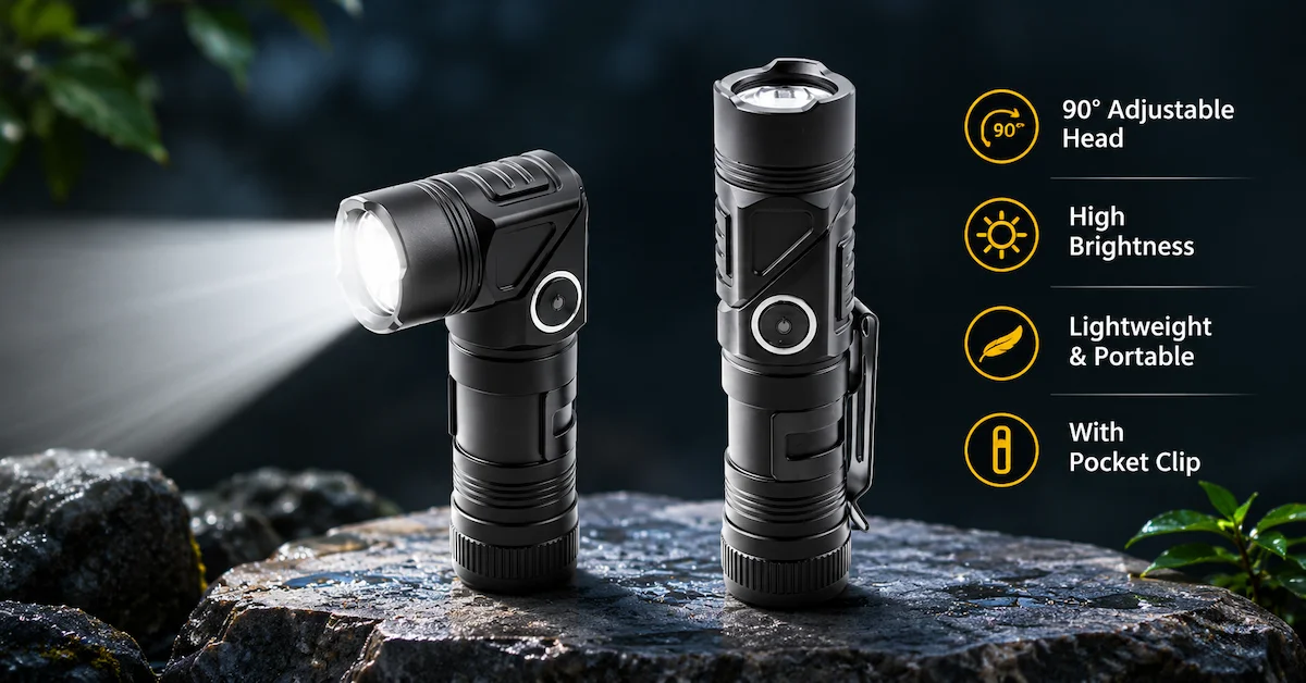
Adjustable-Head SST40 Flashlight
The Brightenlux 1000LM Adjustable-Head Flashlight uses an adjustable-head design, magnetic tail, and Type-C charging.
If a brand requests a different head-angle arrangement, engineers should examine the moving interface, component clearance, and usability throughout the intended movement range.
BT-FL8104: Dual-Power Flashlight
The Brightenlux BT-FL8104 Twist-Focus Flashlight supports a published 18650 rechargeable battery arrangement or an alternative three-AAA configuration.
This provides a reference for discussing battery-related mechanical interfaces.
Different power configurations should never be assumed interchangeable without product-specific engineering approval.
Choosing a reference model
The most suitable platform is not necessarily the brightest model.
Buyers should prioritize the existing architecture closest to their required mechanical features.
6. How Should Engineers Control Tolerances and Fit?
Dimensional tolerances describe permitted variation.
They are particularly important when several components must align or move relative to one another.
Why nominal clearance is insufficient
Suppose a design requires an optical component to maintain a specific position relative to an LED.
That position may depend on several manufactured dimensions.
Even when individual parts meet their drawings, their combined dimensional variation can influence the final assembly.
Illustrative tolerance stack-up
Consider a hypothetical assembly with three contributing dimensions:
| Component | Illustrative Tolerance |
|---|---|
| Housing feature | ±0.12mm |
| PCB support position | ±0.10mm |
| Optical component seat | ±0.08mm |
| Total worst-case accumulation | ±0.30mm |
For a simple linear worst-case stack, the absolute tolerance contributions are added:
0.12 + 0.10 + 0.08 = 0.30mm
This is an educational example, not a Brightenlux product drawing, manufacturing tolerance, or test result.
The actual dimensional model must reflect the geometry, assembly direction, and functional relationship of the specific design.
Define functional references
Engineering teams should identify the surfaces and features that establish the location of critical components.
These references help connect design intent to manufacturing inspection.
Use appropriate geometric tolerancing
The official ISO 1101:2017 standard on geometrical tolerancing establishes a standardized language for specifying geometric characteristics such as form, orientation, location, and run-out.
For custom flashlight engineering, consistent geometric specifications can help communicate requirements for relevant housing and assembly features.
The standard does not provide universal tolerance values for flashlight parts.
Those values must be established according to the product's actual design and manufacturing requirements.
Verify the physical result
The prototype should be measured and functionally evaluated against the approved design.
A drawing review alone cannot establish that a moving mechanism, charging interface, or lens assembly will operate correctly.
7. How Do Materials and Manufacturing Methods Affect Assembly Fit?
A flashlight's mechanical design depends on the processes used to produce its components.
Machined aluminum housings
Aluminum is frequently used for flashlight bodies because of its strength, machinability, and ability to support durable finishes.
Machining operations may create threads, mating surfaces, battery compartments, and features used to position electrical or optical components.
The manufacturing plan should identify which dimensions are critical to product function.
Injection-molded components
ABS, polycarbonate, and other polymers may be used for suitable housings, mounts, covers, or internal parts.
Material properties and molding conditions can influence dimensional stability and final part geometry.
A molded component should be evaluated in its intended assembly rather than judged only by visual appearance.
Surface finishes
Anodizing, coatings, and other finishes may affect dimensions, appearance, and contact interfaces.
The finished part—not only the unfinished substrate—must satisfy the relevant assembly requirements.
Optical components
Reflectors, lenses, and LED mounting features require appropriate positioning.
A change to the optical system may affect both mechanical fit and beam performance.
Sealing materials
Gaskets and sealing elements require suitable materials, groove geometry, and compression arrangements.
Their suitability depends on the finished enclosure design and intended conditions.
Manufacturing Considerations
| Component | Common Design Consideration | Validation Focus |
|---|---|---|
| Aluminum housing | Machined features and finishes | Critical dimensions and mating fit |
| Polymer cover | Molding variation | Final assembly and retention |
| Lens or reflector | Optical seating | Position and beam behavior |
| Battery compartment | Mechanical and electrical fit | Approved battery compatibility |
| Charging-port cover | Access and sealing arrangement | Operation and physical fit |
| Switch component | Alignment and travel | Correct actuation |
| Gasket | Compression and location | Intended sealing performance |
| Clip or mount | Material and geometry | Retention and interference |
The correct material and process choices should be based on the specific design rather than a generic claim that one material is always superior.
8. What Is the Best CAD-to-Sample Approval Process?
A practical development process should separate digital design approval from physical sample approval.
Each stage should answer a different engineering question.
Stage 1: CAD and design review
The buyer and manufacturer review the proposed geometry, component arrangement, technical requirements, and critical interfaces.
Potential interference should be investigated before physical prototypes are produced.
Stage 2: Early physical prototype
An early prototype may be used to study ergonomics, part arrangement, cable access, and mechanical movement.
Depending on the manufacturing method, a rapid prototype may not represent the exact properties or dimensional behavior of a production component.
Stage 3: Engineering sample
An engineering sample should incorporate the intended mechanical and electrical configuration as closely as practical.
The buyer should examine critical dimensions, operating features, and interactions between components.
Stage 4: Design revision
Any problems should be recorded with a clear description, relevant measurements, and required corrective actions.
Revised drawings should be identified by version.
Stage 5: Tooling readiness review
Before authorizing tooling, the buyer should confirm that the critical interfaces have been assessed and outstanding engineering risks are understood.
Stage 6: Production-representative verification
After production tooling and processes become available, the resulting parts and assemblies should be checked against the approved specification.
A successful rapid prototype does not guarantee that tool-produced parts will behave identically.
Development Approval Matrix
| Stage | Main Question | Recommended Evidence |
|---|---|---|
| CAD review | Are the intended interfaces properly defined? | Approved drawings and review record |
| Early prototype | Is the concept physically workable? | Prototype observations |
| Engineering sample | Do major functions and interfaces operate correctly? | Sample test report |
| Design revision | Have identified problems been addressed? | Revision history |
| Tooling approval | Is the design sufficiently mature? | Engineering release record |
| Tool-produced sample | Does production tooling reproduce the intended geometry? | Dimensional and functional inspection |
| Pre-production approval | Is the assembly ready for routine manufacturing? | Approved sample and control plan |
Tooling should not be approved solely because the product's appearance has been accepted.
9. How Should Critical Interfaces Be Tested on Real Samples?
Sample testing should connect directly to the product's intended function.
A useful test method describes the setup, equipment, procedure, and acceptance criteria.
Adjustable-head operation
Inspect the full intended movement range.
Check for interference, excessive play, unexpected contact between components, and unacceptable operating resistance.
The required movement characteristics should be agreed for the product.
USB-C cable access
Test the actual approved charging connector and cable arrangement.
Verify that the cable can be inserted and removed correctly when the complete housing and charging-port cover are assembled.
Battery installation
Use the approved battery or battery pack.
Verify mechanical installation, appropriate electrical engagement, and correct product operation.
Unapproved batteries should not be used to demonstrate compatibility.
Clip and accessory fit
Where a product includes clips, mounts, or straps, evaluate the actual accessory interface.
Check whether the attachment interferes with switches, charging access, or intended movement.
Optical assembly
Inspect the seating and alignment of the relevant optical components.
Conduct appropriate beam evaluation after assembly.
Prototype Test Plan
| Test | Recommended Observation | Acceptance Basis |
|---|---|---|
| Charging-port access | Approved cable fits and engages correctly | Agreed connector and housing specification |
| Adjustable-head movement | Full intended movement is possible | Defined functional range |
| Lens assembly | Components seat and align correctly | Approved drawing and optical requirements |
| Switch operation | Button functions after full assembly | Approved operating specification |
| Battery installation | Approved cell fits and functions correctly | Battery and compartment specification |
| Clip installation | Mounting and removal are appropriate | Approved accessory requirements |
| Magnetic mounting | Intended mounting performance is achieved | Agreed mounting conditions |
| Finished housing | Parts assemble without unacceptable interference | Controlled dimensional requirements |
These checks are proposed engineering practices, not model-specific test results reported by Brightenlux.
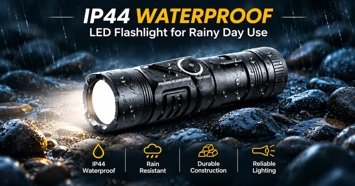
10. How Should Waterproofing and Charging-Port Changes Be Verified?
A structural modification can affect the performance of a finished enclosure.
This is particularly relevant to products that use seals, covers, threaded interfaces, or externally accessible charging connectors.
Charging-port geometry
If an OEM project changes the charging-port position or surrounding cover, engineers should review both mechanical access and the intended protective arrangement.
A correctly positioned connector does not automatically establish water resistance.
Sealing interfaces
The performance of a sealing system depends on the complete assembly, including mating surfaces, gasket geometry, materials, and assembly conditions.
Applicable ingress-protection reference
The official IEC 60529 standard for degrees of protection provided by enclosures defines the IP Code classification system.
For custom flashlight manufacturing, it is relevant when a buyer requires a specific enclosure-protection classification.
However, an existing flashlight's published IP rating must not automatically be transferred to a redesigned housing.
Why retesting may be necessary
A change to the charging-port cover, enclosure geometry, gasket, mating surface, or related assembly can affect ingress protection.
Buyers should assess whether the modified product requires appropriate new validation.
Important distinction
A reference to IEC 60529 does not establish that a particular Brightenlux model or custom design has passed a specified test.
Ask for model-specific evidence, the applicable test method, and identification of the tested product revision.
11. How Should Dimensional Quality Be Controlled During Manufacturing?
A successful prototype must be translated into repeatable manufacturing requirements.
That process depends on controlling critical dimensions, components, assembly methods, and approved revisions.
Incoming component verification
Relevant purchased components should be checked against their approved specifications where necessary.
This can include lenses, electrical connectors, switches, sealing materials, and other parts that affect critical fit.
First-article inspection
Initial parts produced through the intended manufacturing process should be compared with approved engineering drawings.
The inspection should focus on characteristics that influence assembly and product function.
Assembly verification
Functional interfaces should be checked after relevant components are assembled.
This helps identify problems that individual-part measurement may not reveal.
Design and process changes
If a component supplier, material, manufacturing method, or critical dimension changes, the buyer and factory should assess the effect on the approved assembly.
Suggested Quality-Control Plan
| Stage | Required Control | Supporting Evidence |
|---|---|---|
| Engineering release | Approved drawings and specifications | Revision-controlled design package |
| Incoming inspection | Critical component conformance | Inspection record |
| First article | Critical dimensional conformity | Measurement report |
| Assembly | Correct interface function | Functional test record |
| Tooling adjustment | Approved geometry changes | Updated drawing and change record |
| Pre-production approval | Representative assembled product | Approved sample |
| Routine production | Agreed inspection characteristics | Production inspection record |
| Repeat order | Approved configuration consistency | Change-control documentation |
Inspection equipment
Depending on the actual components and precision required, suitable methods may include calibrated gauges, dimensional measuring instruments, optical inspection equipment, or coordinate measurement.
The buyer should ask which methods and equipment are available for the proposed project.
Do not assume that every manufacturer has all specialized measurement systems.
12. When Is Custom Tooling Worth the Additional Cost?
Not every flashlight customization requires a new housing tool.
The appropriate approach depends on the engineering difference required and the available existing product platforms.
Compare Three Development Routes
| Development Route | Typical Scope | Main Technical Risk | Commercial Consideration |
|---|---|---|---|
| Existing platform | Approved product with branding or packaging changes | Limited control over mechanical design | Lower potential development complexity |
| Modified platform | Selected new or revised mechanical components | Interface compatibility | Partial engineering or tooling investment |
| New platform | New housing and assembly architecture | Design, tooling and validation uncertainty | Greater development commitment |
Tooling cost is only one part of the investment
The total development cost can include:
- Engineering design and drawing preparation.
- Prototype production.
- Material and component development.
- Tooling manufacture or modification.
- Dimensional and functional testing.
- Tool adjustments.
- Assembly fixtures.
- Inspection preparation.
- Packaging updates.
- Additional validation work.
Avoid late engineering changes
A component changed after tooling manufacture may require tooling modification or replacement.
The commercial effect depends on the affected feature and manufacturing method.
For a broader financial discussion, see the Brightenlux Flashlight OEM/ODM Tooling Cost Guide .
What about MOQ and lead time?
Minimum order quantity and delivery time depend on the product, components, manufacturing methods, tooling requirements, and approved customization scope.
There is no universal MOQ or fixed development schedule applicable to every custom flashlight.
Request a project-specific quotation and milestone plan.
13. What Should Buyers Include in a Custom Flashlight Manufacturing RFQ?
A clear RFQ helps the manufacturer distinguish existing product requirements from new engineering work.
The buyer should specify the intended application and identify which changes are essential.
Recommended RFQ Checklist
| RFQ Item | Information to Provide |
|---|---|
| Company and market | Buyer, destination country and sales channel |
| Intended application | Outdoor, inspection, industrial or general portable lighting |
| Reference product | Existing Brightenlux model or design reference |
| Design changes | Required mechanical and functional differences |
| CAD files | Available 3D models and engineering drawings |
| Critical interfaces | Charging, optics, battery, switch, clip, mounting |
| Materials | Preferred materials and finish |
| Battery | Exact intended cell or pack configuration |
| Product performance | Lighting modes, beam and operating requirements |
| Sealing requirements | Intended enclosure-protection expectations |
| Prototype plan | Samples, measurements and approval stages |
| Quality control | Critical characteristics and acceptance requirements |
| Branding | Logo, packaging and documentation |
| Order requirements | Quantity, target cost and forecast |
| Project schedule | Design, sample, tooling and production milestones |
Ten Questions to Ask a Custom Flashlight Manufacturer
- Which existing flashlight model is closest to the proposed design?
- Which requested changes can be made without new tooling?
- What CAD and manufacturing drawings are required?
- Which mechanical interfaces present the greatest development risk?
- How will critical dimensions and tolerances be agreed?
- Which prototype methods are available for early fit evaluation?
- What evidence is needed before tooling approval?
- How will charging access, movement and sealing be verified?
- How are design revisions and component substitutions controlled?
- What development costs, MOQ, and milestones apply to the final proposal?
Request a Custom Flashlight Engineering Proposal
Ningbo Brightenlux Electric Appliance Co., Ltd. provides portable LED lighting products and offers OEM/ODM customization discussions for international buyers.
For a custom project, begin with an existing reference model or a clearly defined product concept.
Identify the mechanical features that must change and explain why those changes matter to the intended customer.
Provide any available CAD drawings, reference photographs, battery requirements, estimated order quantities, target market, and desired schedule.
Ask Brightenlux to confirm the feasibility of the proposed design, available engineering support, sample requirements, tooling implications, and validation scope.
Browse Brightenlux Flashlight Products
14. Frequently Asked Questions About Custom Flashlight Manufacturing
1. What should I look for in a custom flashlight manufacturer?
Look for a manufacturer that can discuss engineering requirements, identify an appropriate product platform, review mechanical interfaces, provide representative samples, and clarify production and inspection responsibilities. For structural customization, ask how CAD designs, tolerances, tooling changes, and approval records will be controlled.
2. Is a 3D CAD model enough to approve flashlight tooling?
No. A CAD model communicates design intent but cannot prove that all finished components will assemble and function correctly. Buyers should review manufacturing drawings, relevant tolerances, physical prototypes, critical interfaces, and acceptance requirements before tooling approval.
3. Which flashlight components are most important for dimensional fit?
Common critical areas include lens and LED positioning, adjustable-head mechanisms, battery compartments, charging-port access, switches, tailcaps, clips, magnetic mounting parts, and seals. The actual priorities depend on the product architecture and intended application.
4. What is the difference between CAD review and prototype testing?
CAD review evaluates the proposed digital geometry and component relationships. Prototype testing assesses how physical parts fit and operate. Both are useful because a digitally correct assembly may behave differently when actual material properties and manufacturing variation are introduced.
5. How can buyers prevent expensive tooling revisions?
Freeze critical design requirements only after suitable engineering review and physical validation. Define measurable acceptance criteria, record prototype findings, control drawing revisions, and clarify which issues must be resolved before tooling manufacture begins.
6. Can an existing rechargeable flashlight be customized without creating a new housing?
Potentially. Some existing platforms may support branding, packaging, accessories, or selected modifications without a complete housing redesign. The feasible scope depends on the exact model. Structural or electrical changes may still require new components, testing, or tooling.
7. Does changing the USB-C port position affect waterproofing?
It can. Changing the connector location or protective housing may alter the enclosure and sealing arrangement. Buyers should request a review of the complete assembly and appropriate verification of any claimed ingress-protection performance.
8. What does ISO 1101 mean for flashlight design?
ISO 1101 defines a standardized language for geometrical tolerancing. It can support communication of relevant geometric requirements in engineering drawings. It does not prescribe the correct dimensions for a particular flashlight or certify the manufacturer's production quality.
9. How long does custom flashlight prototype development take?
There is no universal timeline. Development depends on the requested changes, design complexity, component availability, prototype method, tooling requirements, and number of necessary revisions. Buyers should request a project-specific schedule with clear engineering and approval milestones.
10. How can I request a custom flashlight quotation from Brightenlux?
Provide the intended application, reference model, required mechanical changes, battery and charging requirements, available drawings, target quantity, destination market, packaging needs, and desired schedule. Contact Brightenlux to discuss design feasibility, samples, tooling scope, and commercial terms.
Conclusion
Selecting a custom flashlight manufacturer requires more than evaluating product appearance, LED brightness, or branding options.
For overseas lighting brands, importers, and OEM product developers, the connection between digital design and physical assembly can determine whether a custom product is practical to manufacture.
A CAD model is an important engineering tool, but it represents only one stage of product development.
Critical interfaces—including optics, adjustable heads, battery compartments, charging ports, switches, and sealing components—must be evaluated through appropriate drawings, dimensional analysis, and representative physical samples.
A well-defined approval process should connect the design to measurable acceptance criteria.
Buyers should verify the most important interfaces before committing to production tooling, document design revisions, and establish suitable inspection requirements for tool-produced components.
The commercial decision should also consider whether an existing flashlight platform can meet the intended market need with fewer modifications.
Brightenlux publishes multiple rechargeable flashlight architectures that can serve as starting points for these discussions, including adjustable-focus, magnetic-tail, right-angle, adjustable-head, and dual-power products.
The most productive next step is to identify the desired platform, document the features that must change, and request a model-specific engineering assessment.
A successful custom flashlight project is not simply one that looks correct in CAD. It is one whose approved components fit, function, and can be manufactured consistently.
For your next product development program, explore the Brightenlux LED flashlight range and contact Brightenlux to discuss available platforms, custom design requirements, prototype evaluation, and manufacturing feasibility.