


A headlamp false trigger test measures unwanted switching while nobody is asking the sensor to operate. A useful preproduction test separates those observations from deliberate hand gestures, uses fixed observation windows and reports the number of valid trials behind each rate. Buyers can then see both nuisance switching and missed commands before agreeing to release the design.
Imagine a wearer tightening a strap and inadvertently switching the light off. That movement needs a different trial from a deliberate switching gesture. The method below separates the two. Its timings and screening limits are suggestions for an engineering agreement, rather than Brightenlux test results.
Turn the feature description into expected behavior
“Motion sensor” on a quotation leaves several questions unanswered. Does a gesture toggle the light, adjust output or select a mode? Can it wake the lamp after manual shutdown? Which switch enables sensing? The operating instructions should settle these points before either party starts counting failures.
The Fenix HL45R instructions provide one concrete example. Its infrared gesture control works within approximately 10 cm, with performance affected by object material and color, ambient light, selected output and waving speed. Objects other than a hand can also cause switching when they cross that area. This explains why a successful hand-wave demonstration alone leaves questions about normal use. The range and operating logic belong to the HL45R. An object-triggered switch can follow that published logic yet be inconvenient in a particular task. The buyer is judging its acceptability for that task, rather than automatically calling it a manufacturing defect.
Brightenlux's 600-lumen dual-XPG2 sensor headlamp page describes a right-side switch that enables motion-sensor mode. Its current instructions and agreed gesture envelope should determine the project's test distances and response timing.
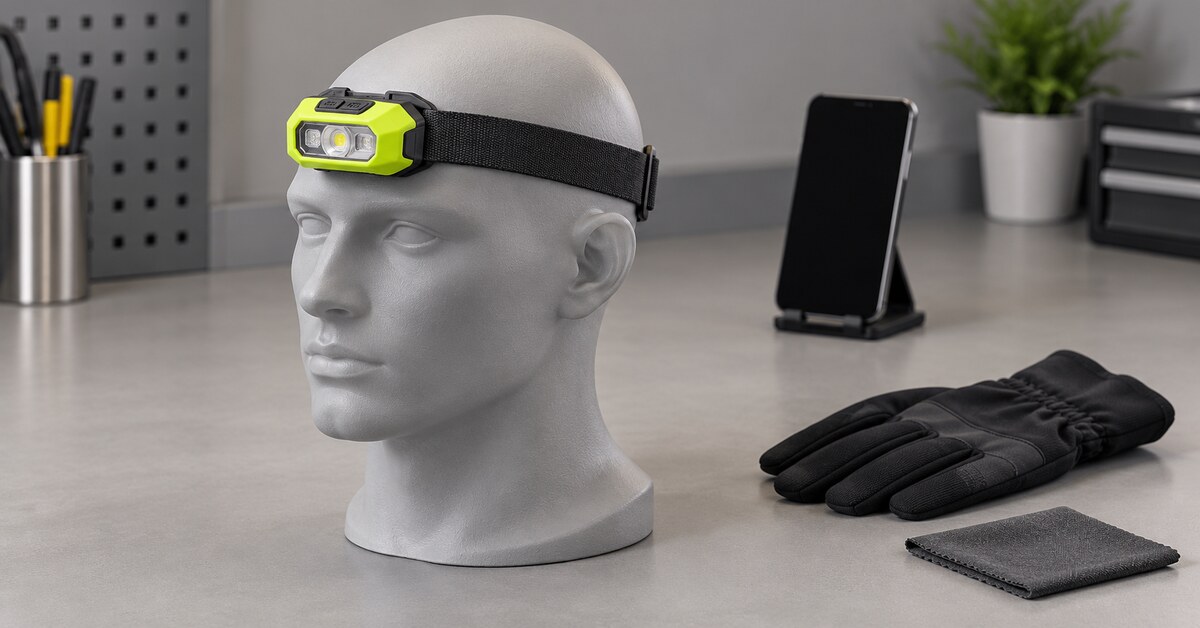
The test sheet needs a starting state and expected behavior for each row. Light-on with sensing enabled, sensor-enabled standby, sensor disabled, manual off and any available transport lock may behave differently. Thermal or low-battery output changes also need their own identification, so an automatic reduction is not misrecorded as a gesture command.
Set up a repeatable headlamp false trigger test
The sample ID connects a clip to the build under review. Its register holds the housing, sensor-cover and board revisions, firmware, battery condition, output and mounting angle. A firmware change during testing creates a separate version in the results.
Ten lamps operated by several people offer a starting development screen, provided the group covers the assembly variations under review. The buyer and supplier choose the eventual sample size for the intended use. Trials confined to one unit say little about variation between units.
Observe nuisance actions without issuing a command
Strap adjustment can be one bench sequence in the headlamp false trigger test. Here is a suggested ten-second trial:
- Put the lamp in the agreed sensing-enabled, light-on state and wait the stabilization period specified for the project.
- Start the trial clock immediately before adjusting the strap. The adjustment contains no deliberate switching command.
- Observe through the ten-second mark. Record every state change, including a brief shutdown followed by a return to light-on.
- Reset to the same stabilized starting state before repeating the movement.
In the log, a hypothetical on-off-on sequence has two event entries. Its window gets one failure entry, regardless of the final light-on state.
Example allocation: ten lamps, twenty valid windows apiece, gives 200 windows for one condition and starting state. Standby needs a separate block with sensing enabled; that block looks for unrequested turn-ons.
Validity check: a planned block of 200 with one unusable clip has a denominator of 199. After one valid replacement, it has 200. The original rejected row and its reason remain available for review.
Time the response to a deliberate wave
Mark where the hand enters the agreed sensing zone and where the gesture ends. An initial timing rule could allow the response from entry into that zone until one second after gesture completion, followed by two seconds of observation for additional responses. The approved interface may justify a different deadline.
The result field has three choices:
- Success. The full trial has only one state change: the required response within the response window. The two-second follow-up after the deadline has none.
- Miss. No state change occurs anywhere in the full trial, including follow-up.
- Wrong/late/extra. Use this entry for an incorrect response, a late response or a repeat. A correct turn-off after the deadline counts as late.
A positive trial with an operator leaving the agreed path can be logged as invalid with its reason. In a nuisance block, however, a planned strap adjustment stays valid when the hand happens to resemble a switching gesture.
Build the matrix around what the wearer does
Ordinary strap adjustment belongs in the main use sequence; a broad sweep can follow as a labeled stress trial. For diagnosis, the first comparison might be bare hand versus one glove with all other settings retained. Outdoor illumination can be added in a later block.
| Test block | Action or exposure to agree | Record with the result |
|---|---|---|
| Wearer movement | Adjust headband, tilt lamp, reach toward forehead, turn head | Starting state, hand path, mounting angle, operator |
| Nearby objects | Pass sleeve, tool handle or tent fabric through a defined path | Object material, color, distance, direction and speed |
| Lighting | Repeat indoors, in darkness and in target outdoor illumination | Measured illuminance where available, source direction, output |
| Gloves and gestures | Repeat deliberate waves using intended gloves and directions | Glove, path, distance, speed and response classification |
| Power and mode | Repeat at agreed battery states and supported outputs | Battery voltage or defined state, active mode, temperature |
| Sensor cover | Compare clean cover with agreed fingerprints or moisture exposure | Exposure method, photographs and cleaning/reset procedure |
| Disabled or locked | Repeat nuisance movements in each documented disabled state | Switch sequence and confirmation of starting state |
For a lighting row, a photograph should show where the source sits relative to the sensor. Add an illumination reading at the sensor plane when available. The same lux value could come from different source directions and optical exposures, so the photograph and setup description remain part of the record.
Moisture trials stay within the agreed conditions for the sample. A damp sensor cover is an observation condition here; an ingress-rating claim requires its separate qualification evidence. Spraying or immersing a lamp beyond the approved conditions would introduce a different question.
A thirty-minute mock task is one possible companion to the short windows, with sensor-enabled time and uncommanded transitions logged throughout. The same troublesome sequence can then be repeated with sensing disabled. Switching that persists calls for investigation of another mechanism. Switching that ceases narrows the investigation without identifying which component caused it.
Calculate headlamp false trigger test rates
Keep failed windows, transition counts and sensor-enabled hours in separate columns. The calculations below use those three totals.
| Measure | Calculation | Details to retain |
|---|---|---|
| False-trigger window rate | Negative windows with at least one unwanted transition ÷ valid negative windows × 100% | Condition, starting state, affected samples and raw counts |
| Missed-gesture percentage | 100 × missed trials ÷ valid positive trials | No state change from gesture entry to end of follow-up; retain path, glove and output |
| Wrong/late/extra percentage | 100 × wrong/late/extra trials ÷ valid positive trials | One classification per trial; retain expected transition, deadline and complete sequence |
| Switching events per sensor-enabled hour | Count of unwanted transitions ÷ sensor-enabled exposure in hours | Event count and enabled-time log; no conversion into a per-trial percentage |
Arithmetic example: three failed windows out of 200 valid windows give 1.5%. If six transitions occur inside them, the two tallies read “3 failed windows” and “6 events.” Lamp IDs and separate on/off event entries remain attached to those totals.
Calculate the limit behind a zero count
The following worked example uses the exact binomial approach described by NIST. Its inputs are zero observed failures and 100 valid, comparable trials:
Probability of zero events = (1 − p)^100
For a one-sided 95% upper confidence limit: (1 − p)^100 = 0.05
Upper limit for p = 1 − 0.05^(1/100) ≈ 0.0295, or 2.95%
Here p is a constant per-trial event probability, and the trials must be independent. Repeated movements on one unit or a mixture of different conditions may not satisfy that model. The upper limit describes uncertainty in this mathematical example; it is not a measured headlamp failure percentage.
Agree the release decision before seeing the counts
Before testing, the buyer and supplier agree which interruptions would stop release, which conditions to run, how much exposure to record and when a trial may be excluded.
The following is one negotiable engineering screen. For each negative condition and starting state, ten lamps receive twenty valid windows apiece; all 200 must be free of unwanted transitions. The positive allocation contains 200 gestures, allowing up to two misses but zero wrong, late or extra responses. The agreed continuous-use block also allows zero unwanted transitions. Before testing, assign the positive trials among lamps, gloves, paths and output modes.
These counts are a project-screening proposal for buyer approval. An agreed pass under this screen is not an industry-standard acceptable percentage, a production-wide reliability estimate or qualification for safety-critical use. The release discussion also needs to examine what failed. A repeated shutdown during an important task can require action even if a combined percentage is low.
If engineering changes the firmware, sensor cover or assembly, the original clips and records stay in the file. The revised configuration is retested against the failed condition and relevant regression cases. Swapping out the troublesome unit without documenting it would obscure the evidence.
Connect the report to the configuration being ordered
The approval package for the headlamp false trigger test includes the protocol revision, sample register, setup photographs, videos, raw trial log, calculations, exceptions and release decision. An event should be traceable to the lamp, condition, starting state and observed response.
Freeze the approved configuration before production transfer. Changes to firmware, sensing components, cover geometry or assembly position then trigger a review of affected tests. The OEM headlamp development guide connects this sensor evidence with the broader project.
FAQ
What counts as a false trigger?
An uncommanded transition in a valid negative window. Name the monitored transition, such as activation or shutdown, before testing.
Where does a missed wave belong?
In the positive-trial count. A trial with no transition is missed; a delayed response belongs in the wrong/late/extra category.
Must every model be tested at 10 cm?
The model's agreed gesture envelope sets the distance. The Fenix example illustrates its own operating range.
Why separate standby from manual off?
A lamp that looks off can still be waiting for a wave. Manual shutdown may end sensing instead. The instructions determine the expectation for each state.
Can all gloves share one result?
Keep relevant glove types identifiable. Material and gesture-path records make a combined result interpretable.
Does an IP rating demonstrate sensor reliability?
An ingress rating does not supply a false-trigger rate. Command behavior needs its own defined exposure and observation.
What does zero out of 200 establish?
Zero observed events in the reported trials. A broader reliability claim needs a suitable sampling design and uncertainty assessment.
Can an automatic fixture replace operators?
A fixture can reproduce agreed paths and states. Retain human-use trials for movements and conditions it cannot represent.
May accidental hand movements be excluded?
They remain valid when they are planned nuisance exposures. Trial exclusions follow the agreed validity rules.
What should the buyer send with an inquiry?
Include intended tasks, market, quantity, gesture expectations and acceptance matrix. Request the current instructions and configuration-specific sample evidence.
Conclusion
In a headlamp false trigger test report, a reviewer should be able to follow a failed count back to its lamp and video. Keep the raw log and sample-level results with the acceptance policy.
For a Brightenlux project, send the application, market, quantity, customization needs and test matrix. The next step is to confirm operating instructions and the sample configuration, so approval evidence can be matched to the headlamp that will be ordered.